What it does
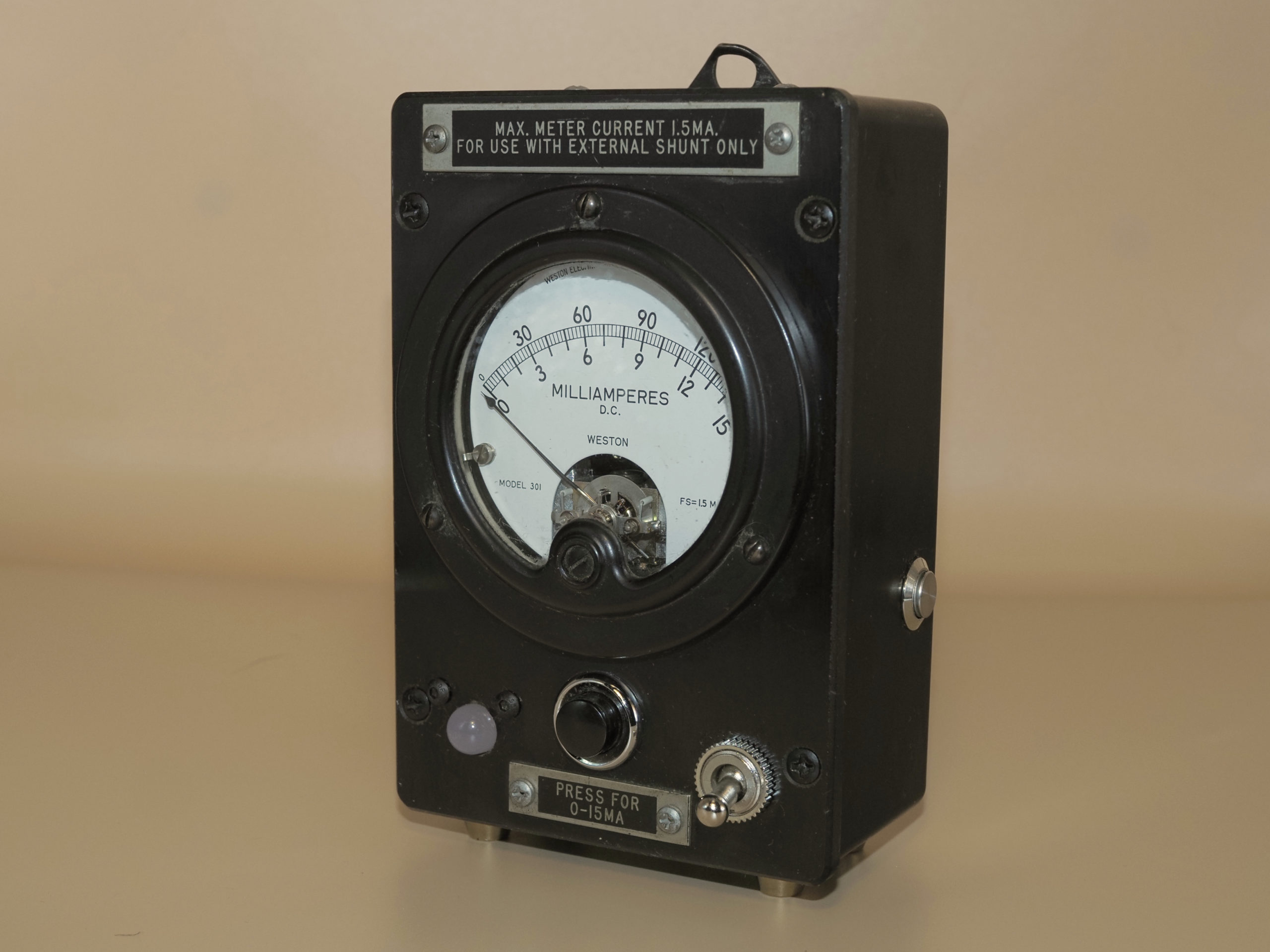
This gadget uses a sensor to measure the indoor temperature or humidity, and displays the reading on an RCA Type 587 Plate Current Meter. The original internal organs of the meter have been removed and replaced by a modern sensor and microcontroller.
About the meter
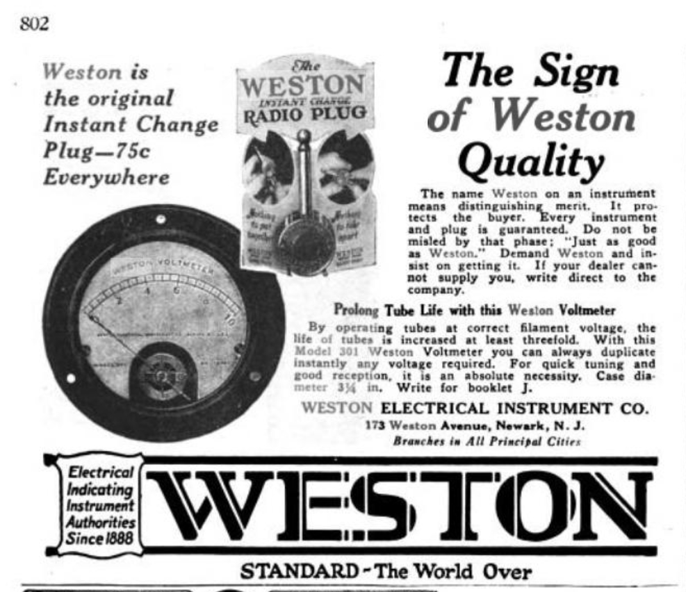
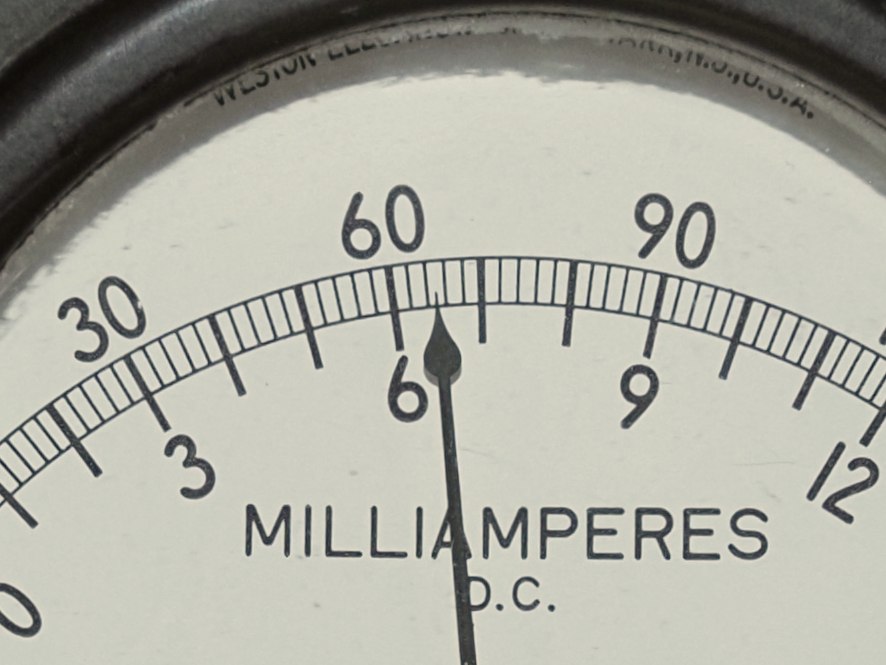
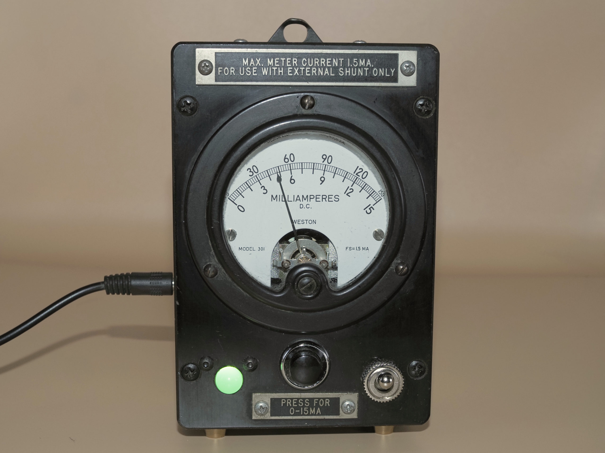
The display meter is a Weston model 301, one of the most commonly-used meters of this era. Weston model 301 meters appeared in a wide range of equipment dating back at least to the 1920’s, and were used for measuring both voltage and current. The meter in this gadget is used to measure current up to 1.5 milliamperes.
Provenance
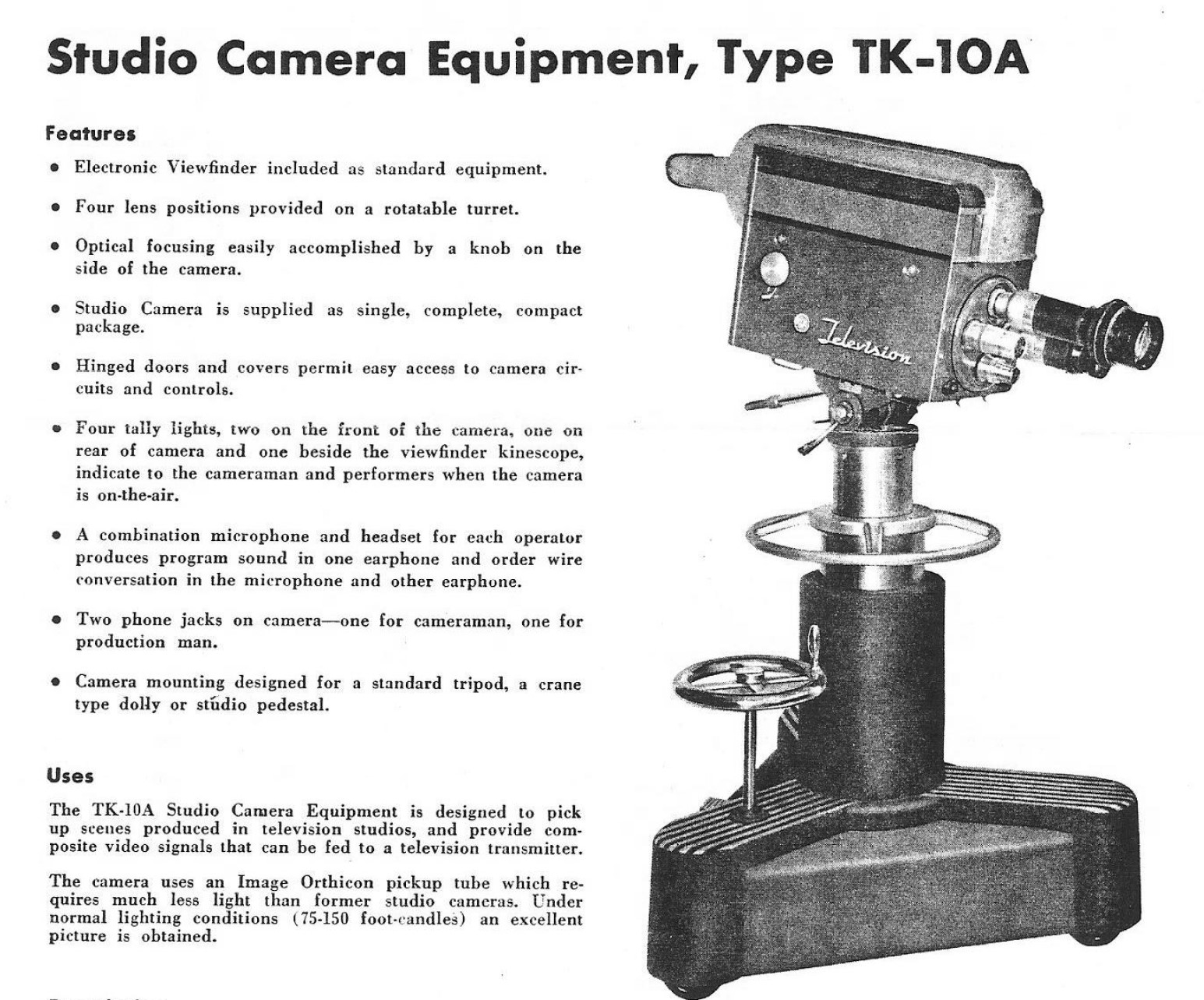
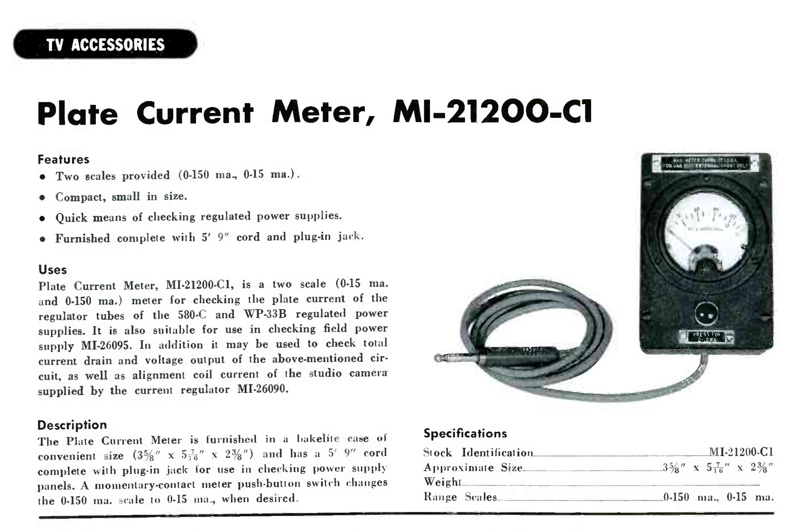
Studio television cameras of the 1940s and 1950s were monstrous beasts, needing large vacuum-tube power supplies to run the video amplifiers in the camera chain. A classic example is the RCA TK-10A, developed in 1947, and used through the 1950s. The RCA Type 587 Plate Current Ammeter was used to measure the current flowing in the vacuum tubes employed in RCA 580-C and WP-33B power supplies, which were housed in units located in the studio control room. Since vacuum tubes were notoriously cranky, a meter such as the Type 587 was used to make sure the power supplies were staying within their prescribed operating limits. It was crucial for the quality of the output voltage to be maintained as the vacuum tubes aged.
How to use the gadget
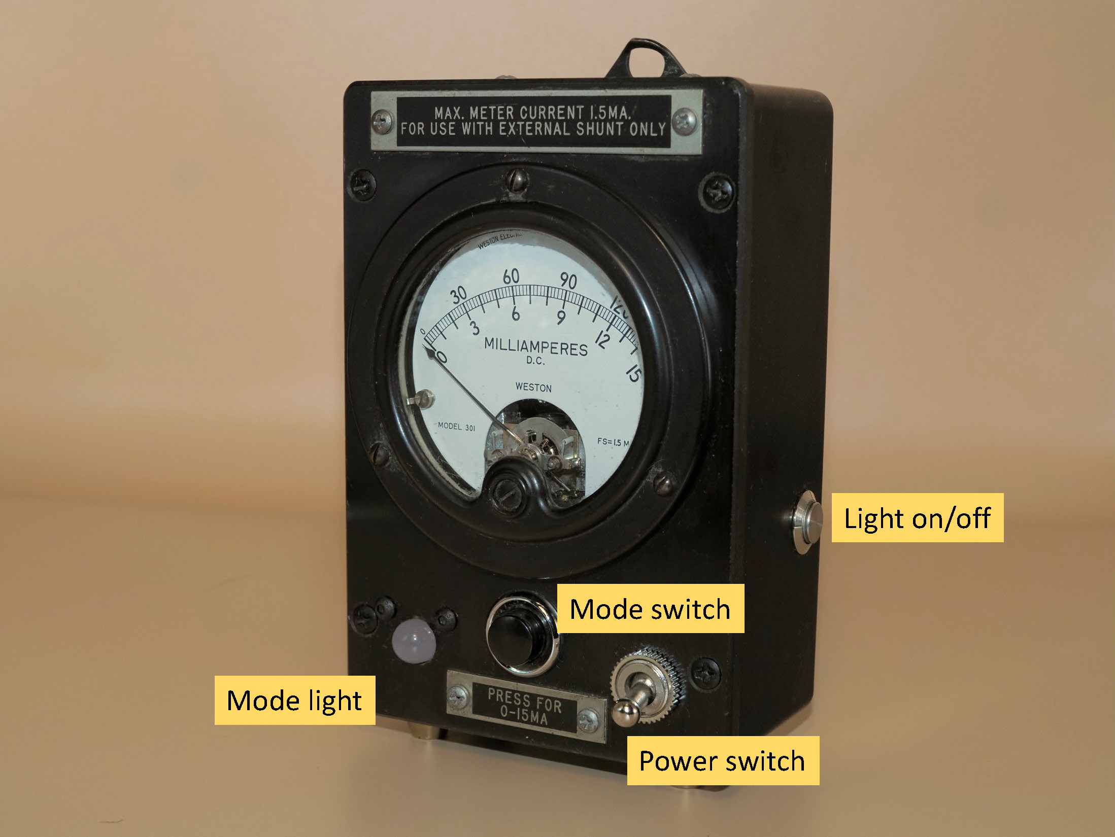
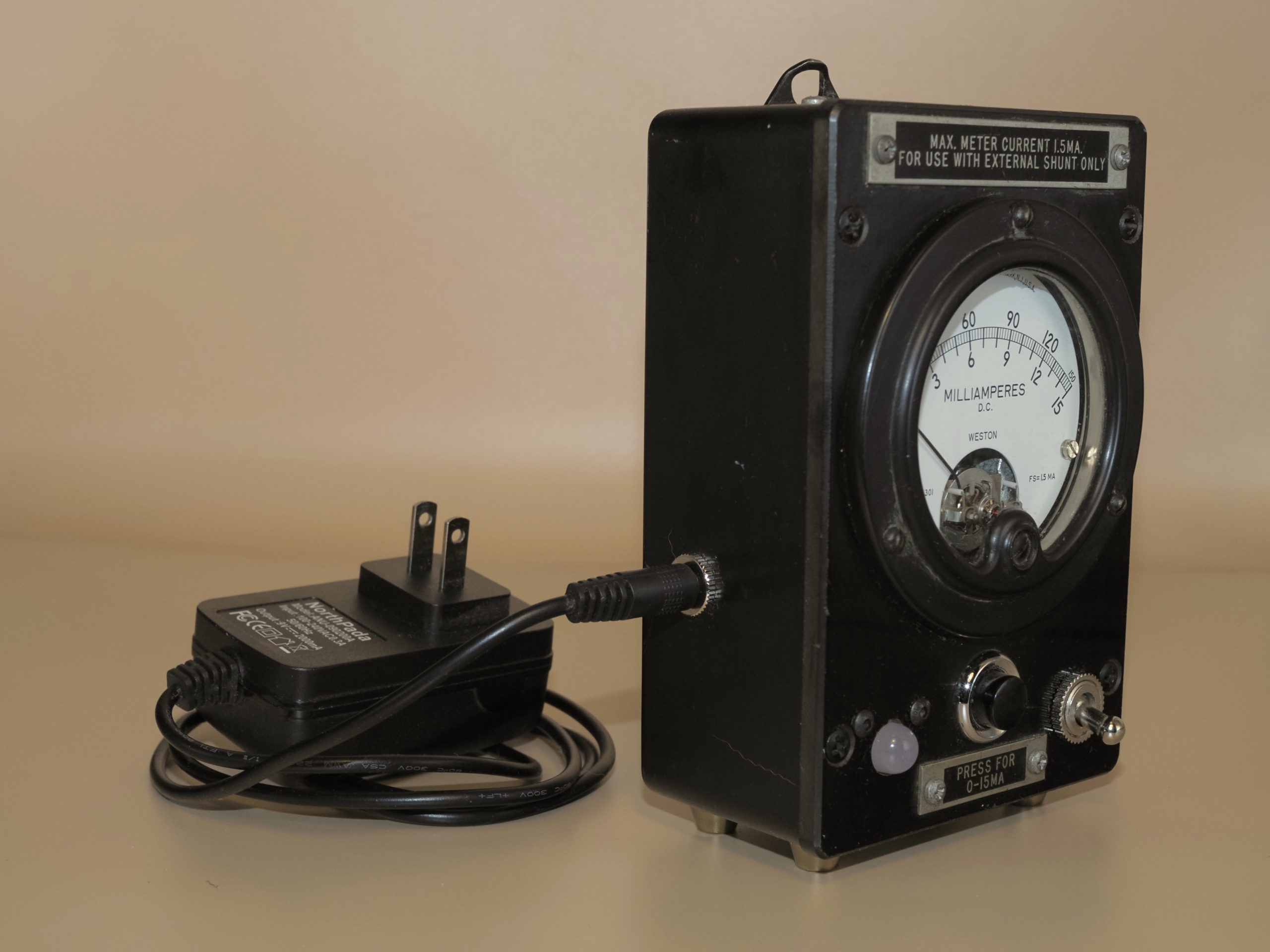
This gadget is very easy to use. The power jack is located on the left side. Start by connecting a 9V power supply to the power jack (see below). Then turn the power switch to the “on” position (up).
The measurement mode (temperature or humidity) is indicated by the mode light — red for temperature and green for humidity (think red for hot!) To toggle between modes, press and hold the spring-loaded mode switch until the light blinks and changes to the opposite color. If the light is too annoying, you can turn it off using the light on/off switch. The mode light will still blink the proper color when the mode switch is pressed, but will then switch off.
The sensor is located on the bottom of the unit, behind a hole. You can see the sensor through the hole. Be sure not to block the hole since the sensor needs access to the air surrounding the unit. If you’re confused about how to tell which mode the gadget is in, just breathe into the sensor hole. This raises the humidity quite a bit, without raising the temperature much. If you see the needle go up towards 100%, you know that the setting is on humidity.
Care and feeding
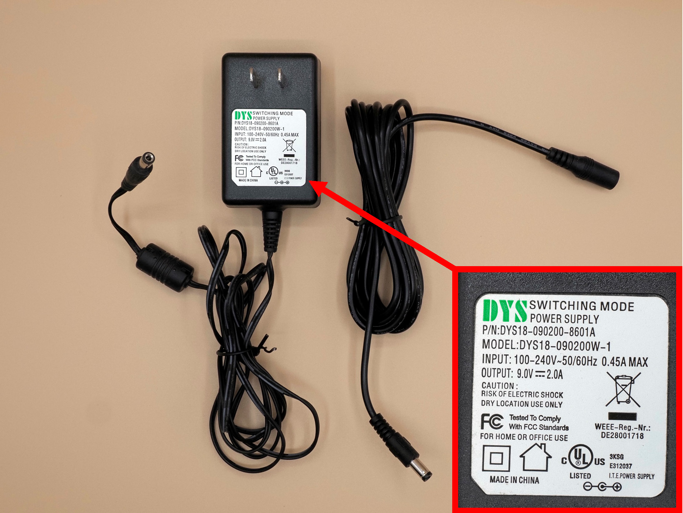
You must power the gadget using a 9V DC power supply with a standard 2.1mm center-positive connector. Any supply with a current rating of 1A or higher should be fine (see picture). These power supplies are ubiquitous — just search for “9V arduino power supply” on Amazon or any other web commerce site and you will find numerous vendors. Just make sure the supply is 9V center-positive, or you will damage the controller. You can also find nice extension cords for these power supplies, as shown in the picture.
Clean the gadget as you would any appliance. You can use glass cleaner on the meter glass, but be careful! The glass on any one of these these meters may be loose, and if you press too hard you may dislodge it.
Reading the meter
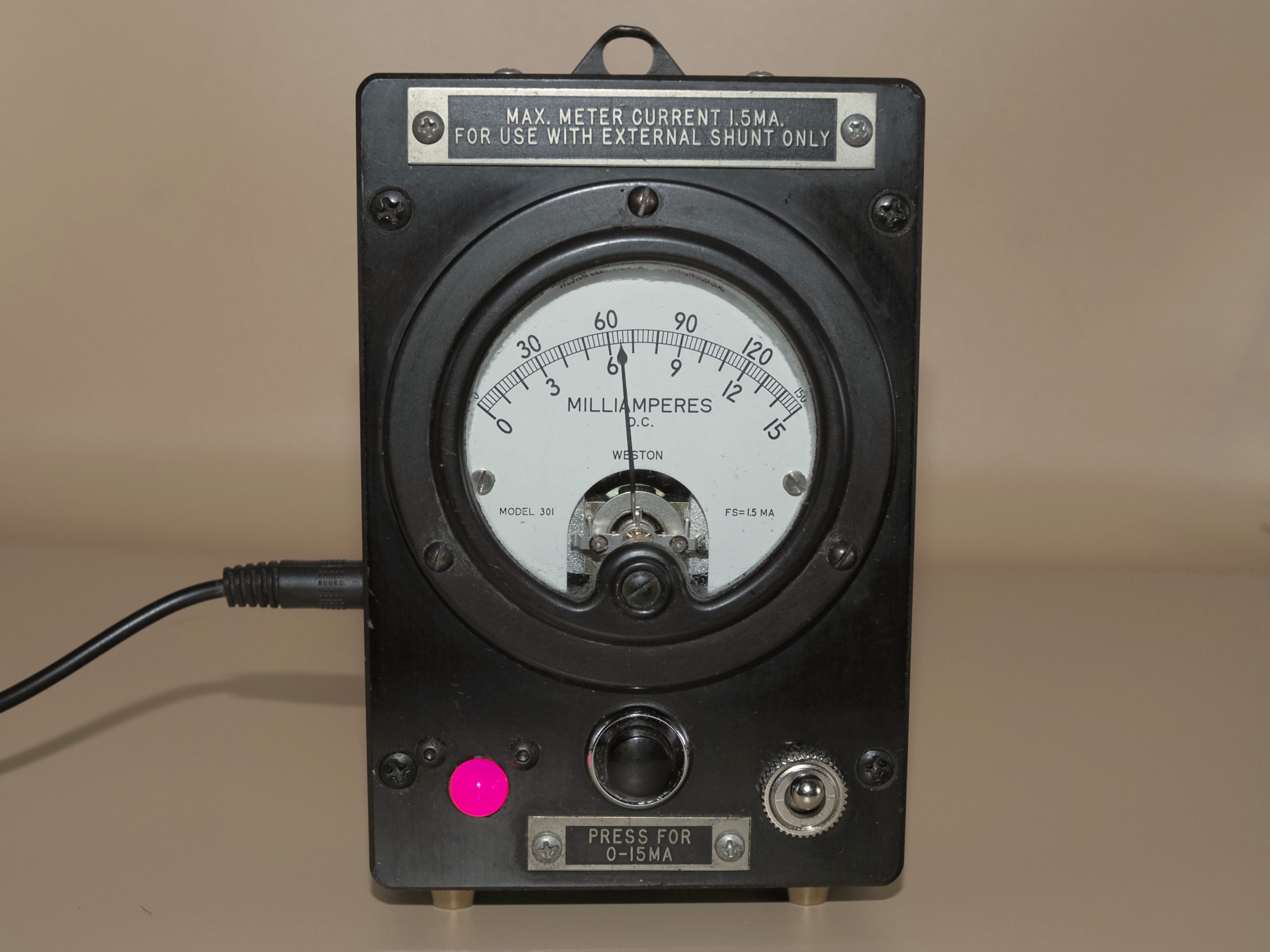
The scale of this meter was originally designed to display current in the range 0-15 or 0-150 milliamperes, depending on whether the spring-loaded button was pressed. I have calibrated the output of the controller so that the same display indicates either temperature in the range 0-100 degrees Fahrenheit, or relative humidity in the range 0-100%. In the two examples shown here, the reading is either 65 degrees (top picture), or 48% (bottom picture). You can use the top scale directly, or use the bottom scale and multiply by 10.
Often during the summer months the temperature and humidity readings are very close, and if the needle changes only slightly when you change modes you may wonder if the gadget is actually working. To test, switch to the humidity mode and breath into the sensor hole, as described above.
Accuracy
This gadget uses a high-precision Silicon Labs Si7021 sensor. Nevertheless, this is not a laboratory instrument, and you should not expect highly accurate readings. My guess is that the temperature should be good to about 2 degrees, and the humidity to about 5%, over the expected indoor range of readings. See the section below on the gadget operation for more information about accuracy.
Longevity
The Weston ammeter is probably 75 years old. Some of the meters in my projects are more than 120 years old, and amazingly, they still work. Most old meters are very well constructed and were designed for continuous use over a long haul. I hope that the Weston meter has many more years of useful service in its future, but there’s no way to tell when it might crap out. If it stops working, at least the meter is a beautiful antique worth displaying!
How the gadget works
The Weston meter was designed to display up to 150 milliamperes of current. The meter itself is only rated to 1.5 mA, so it depended on an external shunt to bypass most of the current. This shunt was located in the control unit that contained the power supplies. I have removed the interior workings of the Plate Current Meter and installed a Silicon Labs Si7021 high-precision temperature/humidity sensor into the housing, with the detector placed against a hole to allow access to the surrounding air. The sensor has a manufacturer-rated accuracy of +/- 1 degree Fahrenheit, and +/- 3% relative humidity. Readings are taken using an arduino nano and displayed on the meter using a simple resistor voltage divider against the internal resistance of the meter. The voltage is controlled using PWM on a digital pin. These old meters are notorious for being both nonlinear and out of calibration, so I calibrated the meter through its range by using a 4th-order polynomial to best-fit the measured temperature or humidity to displayed current. In practice, considering the accuracy of the sensor and the age of the meter, I would expect the displayed temperature to be accurate to about 2 degrees and the humidity to around 5%. I would also expect that over time the performance of the meter will degrade and drift a bit. Even so, I wouldn’t be surprised if the more probable failure point is the solid-state arduino controller rather than the mechanical ammeter!