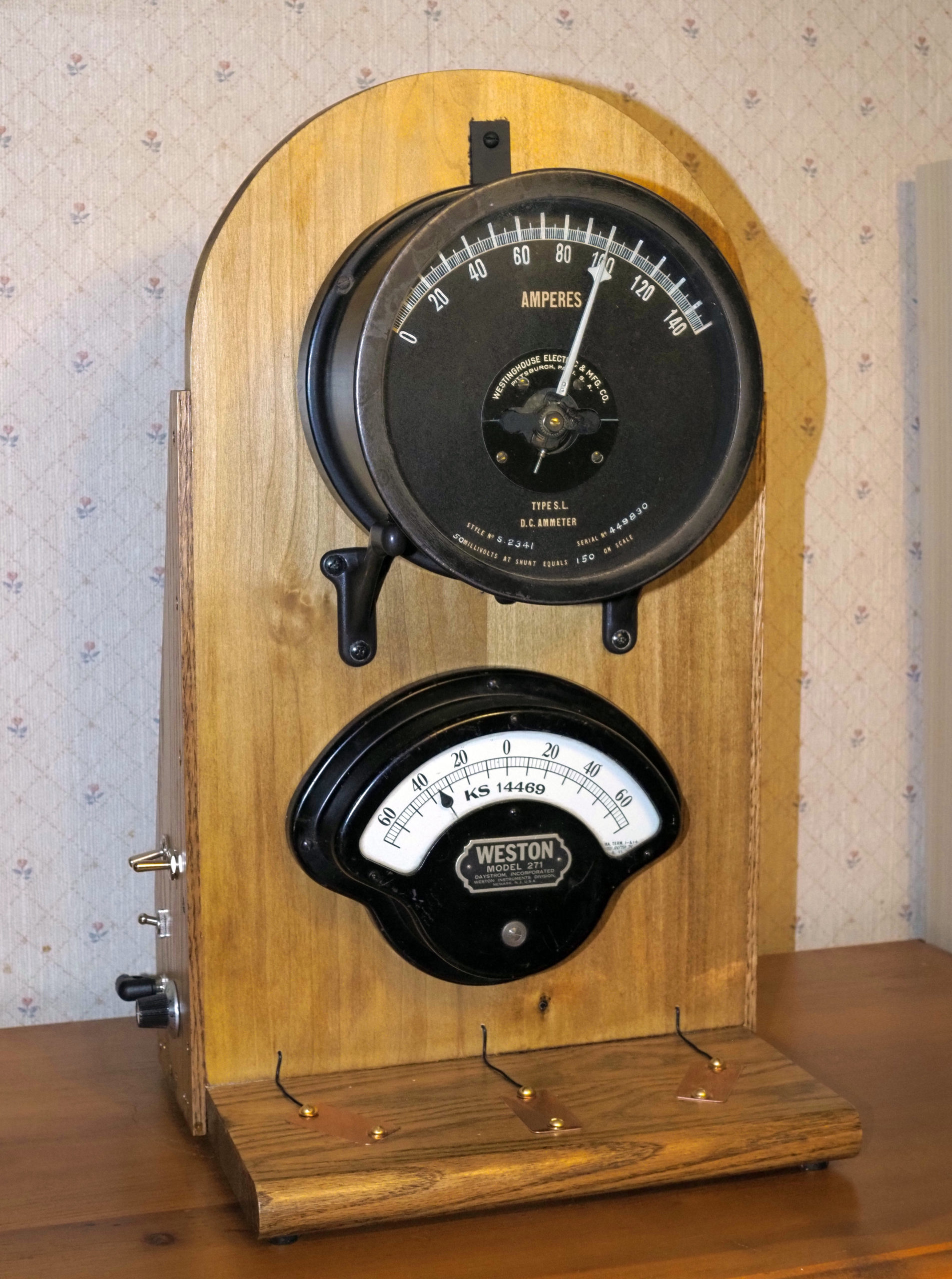
What it does
This gadget uses an accurate real-time clock to display the hour on the top meter and the minute on the bottom meter. It also chimes on the quarter, half, and three-quarter hour using the Westminster chimes through a speaker on the right side. The clock ticks each second using the same speaker. A volume knob controls the loudness of the ticking and chimes.
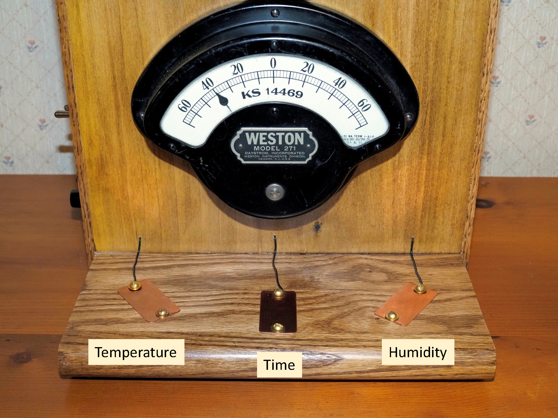
The clock also uses a sensor to measure the indoor temperature and humidity. By touching one of the three pads, the clock will speak the temperature, time, or humidity in a female voice. The loudness is controlled by the volume knob.
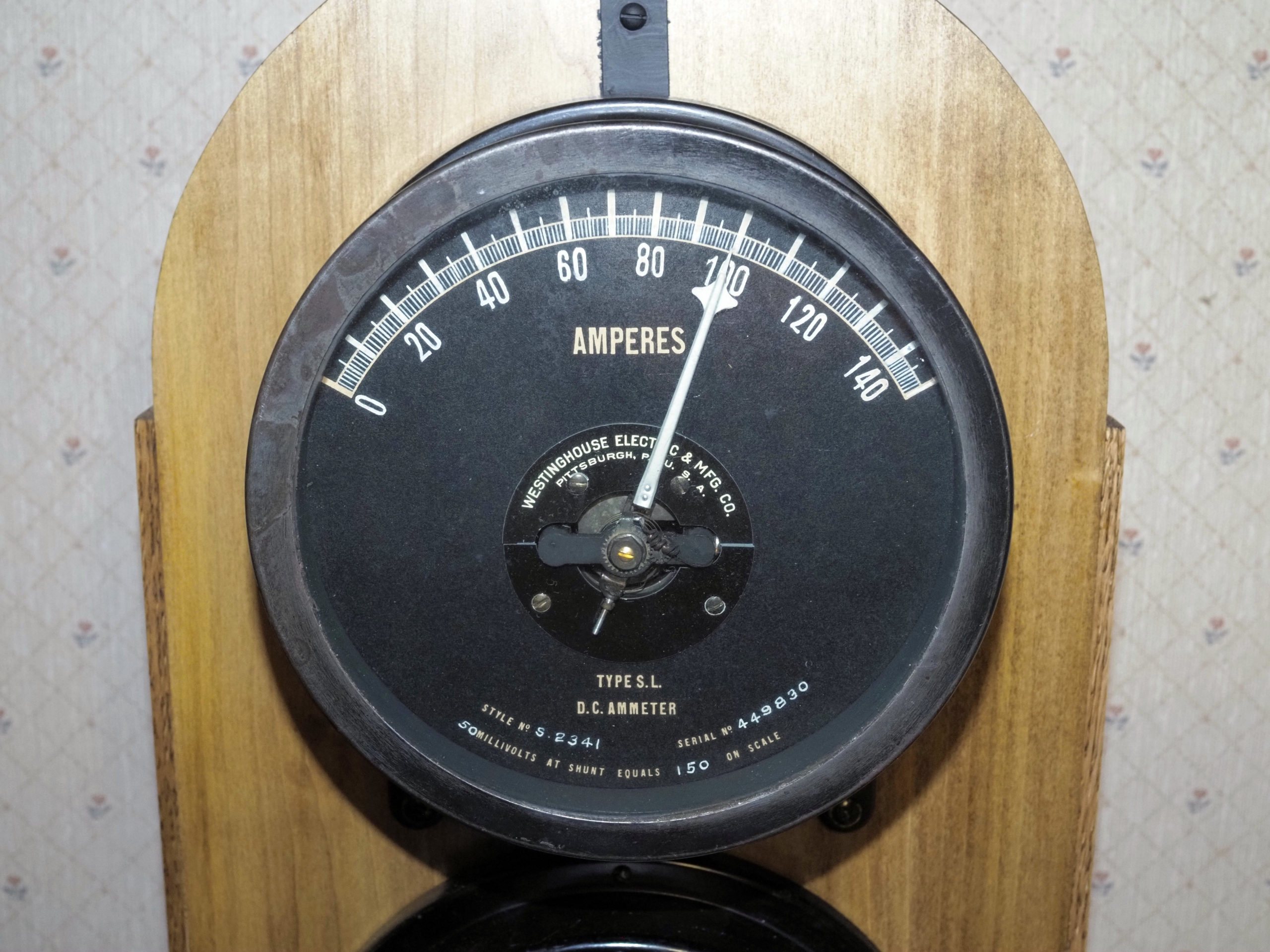
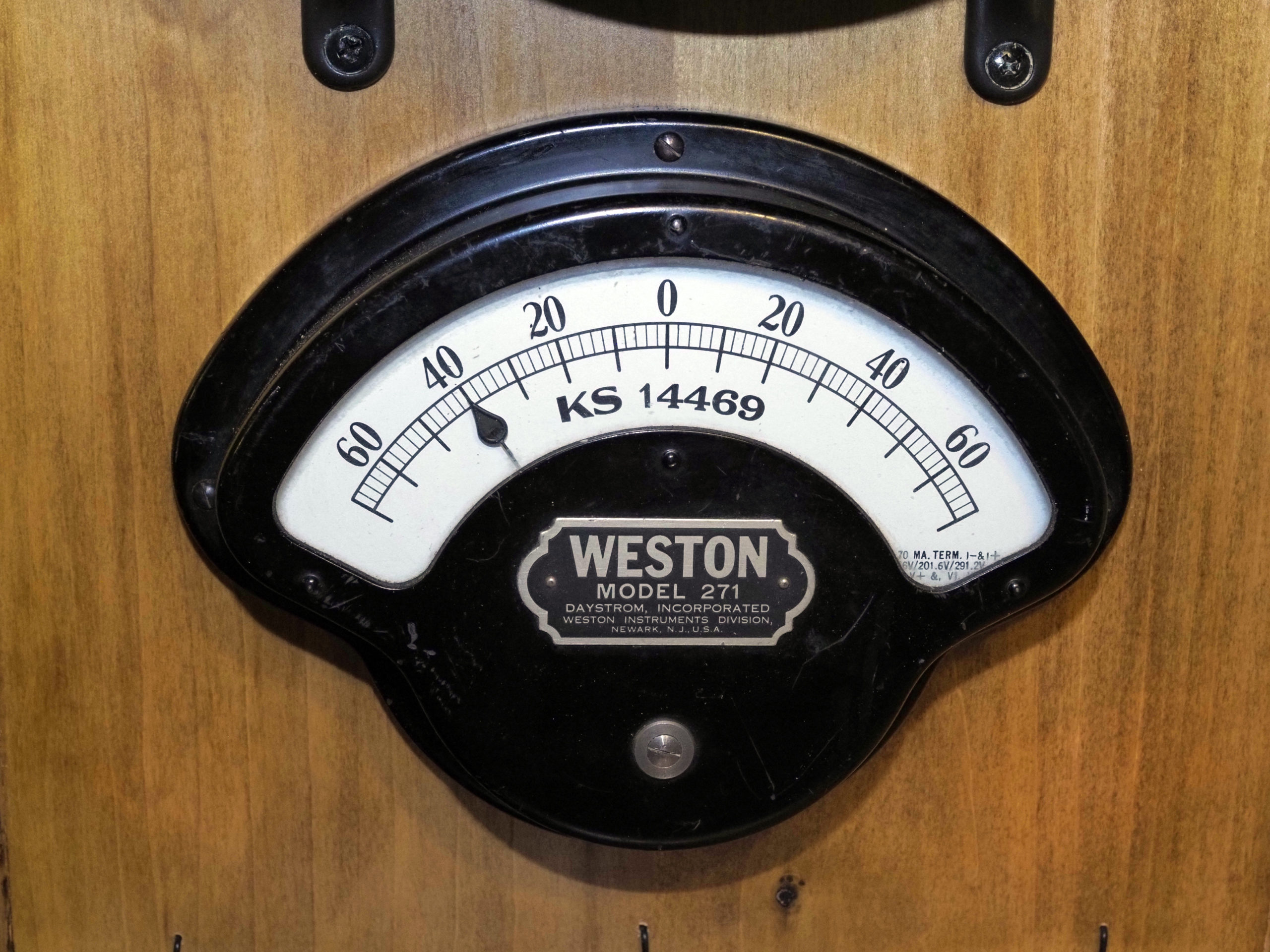
The top meter is a circa 1910s Westinghouse 7-inch switchboard meter. The bottom meter is a 1950s era Weston meter from a portable measurement instrument.
Provenance
Westinghouse meter
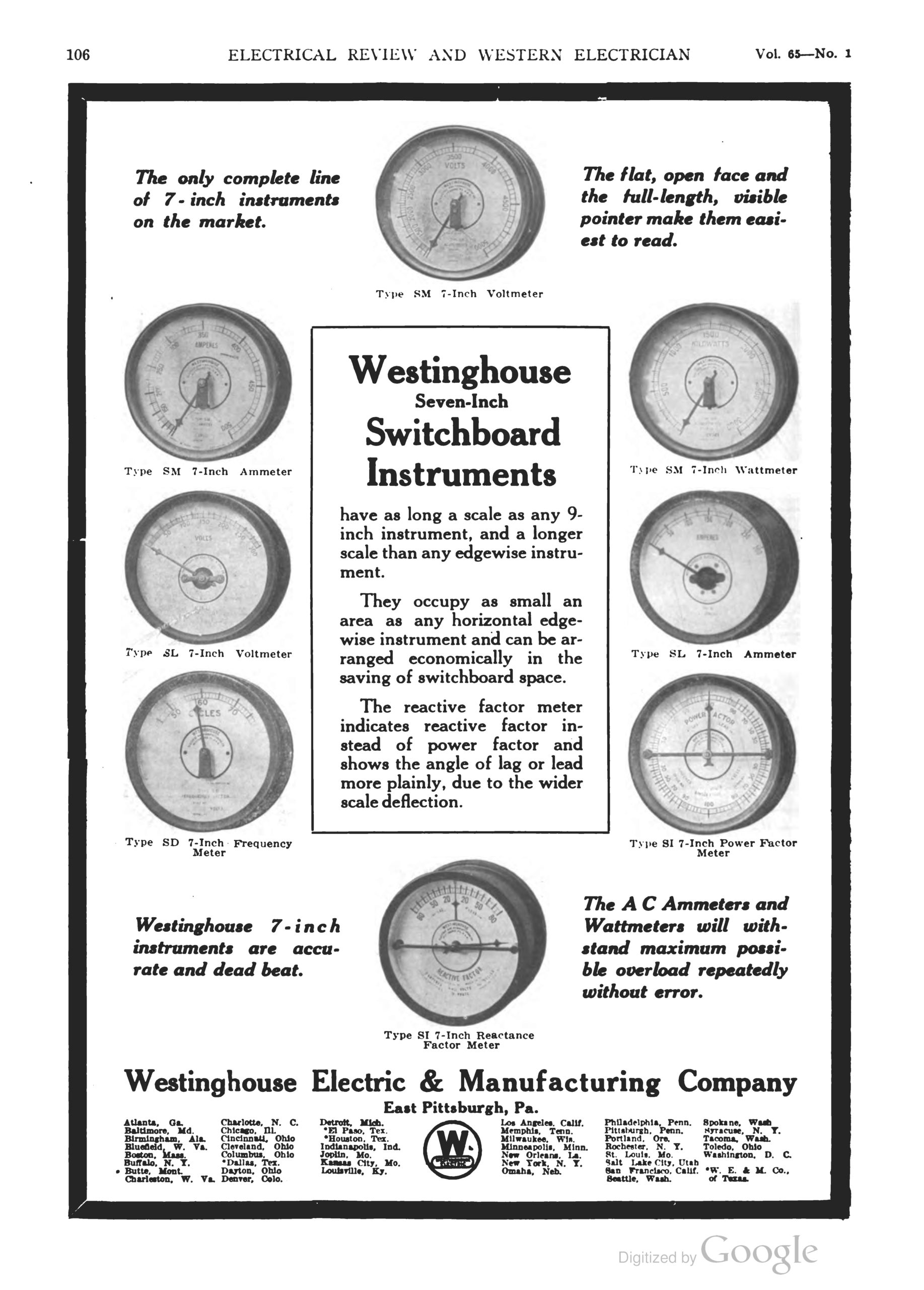
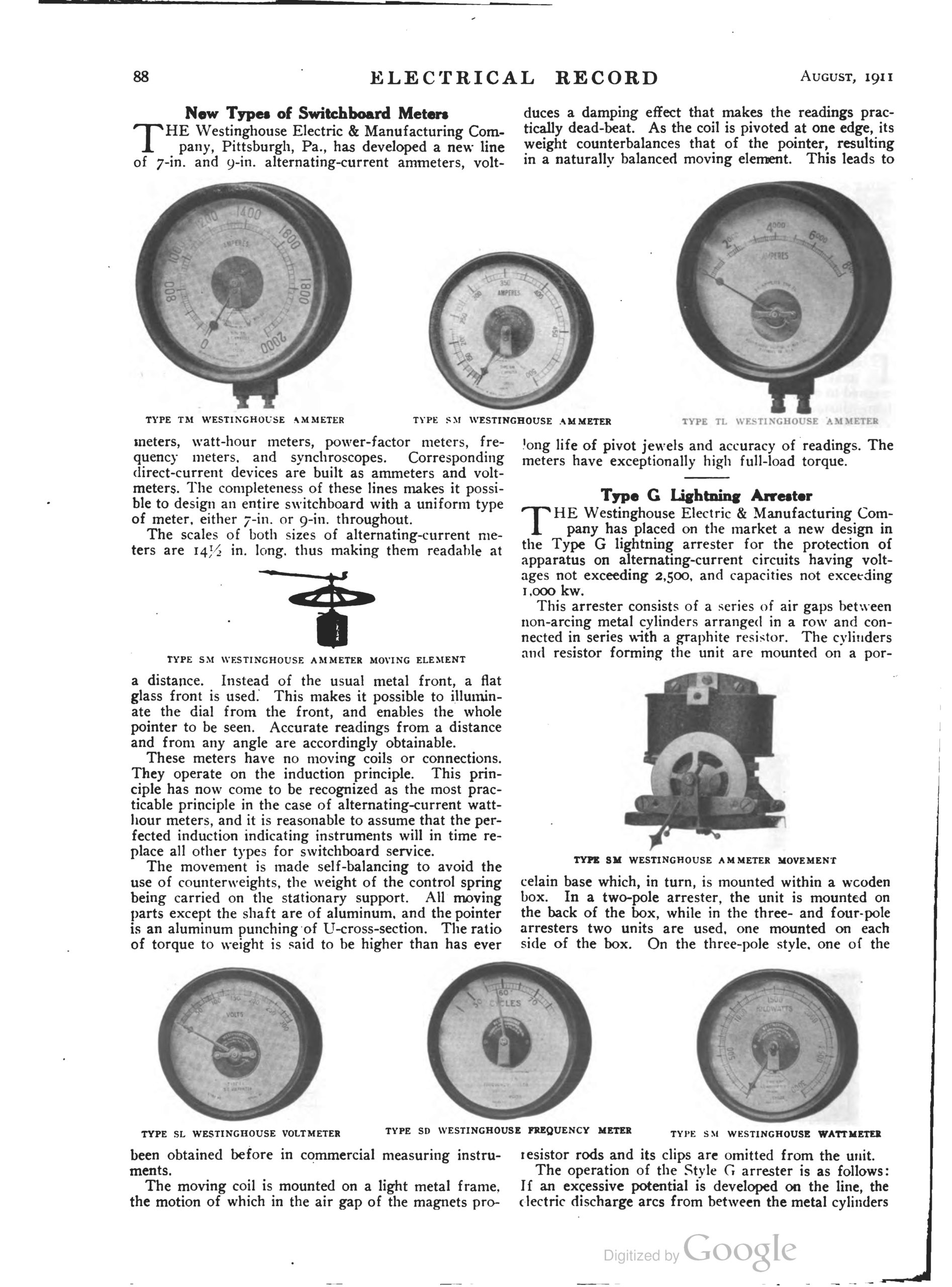
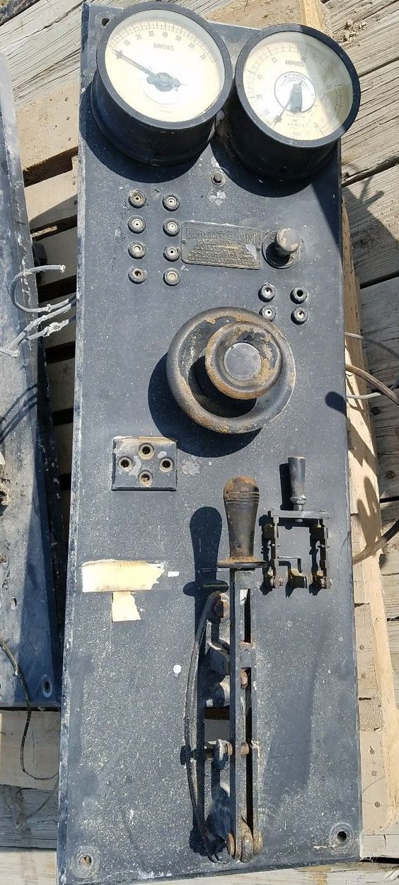
The Westinghouse meter is a classic 7-inch type SL switchboard meter introduced around 1911. Click on the image to the right to read an article from the July, 1911 issue of the Electrical Record describing their introduction. Switchboard meters were typically used in large electrical installations, such as power houses, in factories, and in the basements of office buildings and hotels. Because this is a large-current DC ammeter, it was most likely used for an electric railroad, in a manufacturing plant, or on a ship, since by the 1910s most lighting and home electricity was AC. Switchboards typically had numerous panels, each one with its own switch and a variety of meters to monitor voltage, current, and power. A typical panel using Westinghouse type SL meters is shown in the image to the right. The switchboards were used to send electricity to various parts of a building, or from a power house to different circuits for transmission.
These types of meters may have been manufactured for several years, so it is difficult to know the exact age of the meter in the clock. A July 4, 1914 advertisement in the Electrical Review shows that they were still being manufactured then. My guess is that the meter used in the clock is at least 100 years old. Note that all of the type SL meters shown here have white faces with black lettering. I was not able to locate a picture of a meter with a black face, as used in the clock. I would guess that the buyer could select either a white or a black face upon ordering.
 Advertisement from the July 4, 1914 issue of the Electrical Review.
Weston meter
The bottom meter on the clock is a Weston Model 271. Edward Weston formed the Weston Electrical Instrument Company in 1888 in Newark New Jersey. The Weston Company was a major manufacturer of electrical meters for nearly 100 years, making some of the earliest commercial devices. The model 271 was commonly used in portable laboratory instruments, such as voltmeters and ammeters, but was also used in specialized equipment, such as counters, frequency meters, and tachometers. It is unknown what the particular meter in the clock was used for. The Weston Company was sold off to Daystrom in 1954, who continued to use the Weston brand. In 1962, Daystrom was absorbed by Schlumberger. Since the meter used in the clock is branded as Weston but includes the Daystrom name, it was probably manufactured between 1954 and 1962.
How to use the gadget
Display
The time is always displayed on the two large meters. See the section below describing how to read them.
Audio
There is a speaker on the right side of the clock to provide audio information. The clock ticks every second (approximately), and the clock chimes on the quarter, half, and three-quarters hours. The loudness is controlled as described below. Temperature, time, or humidity is spoken when a capacitive pad is touched. See below for more information.
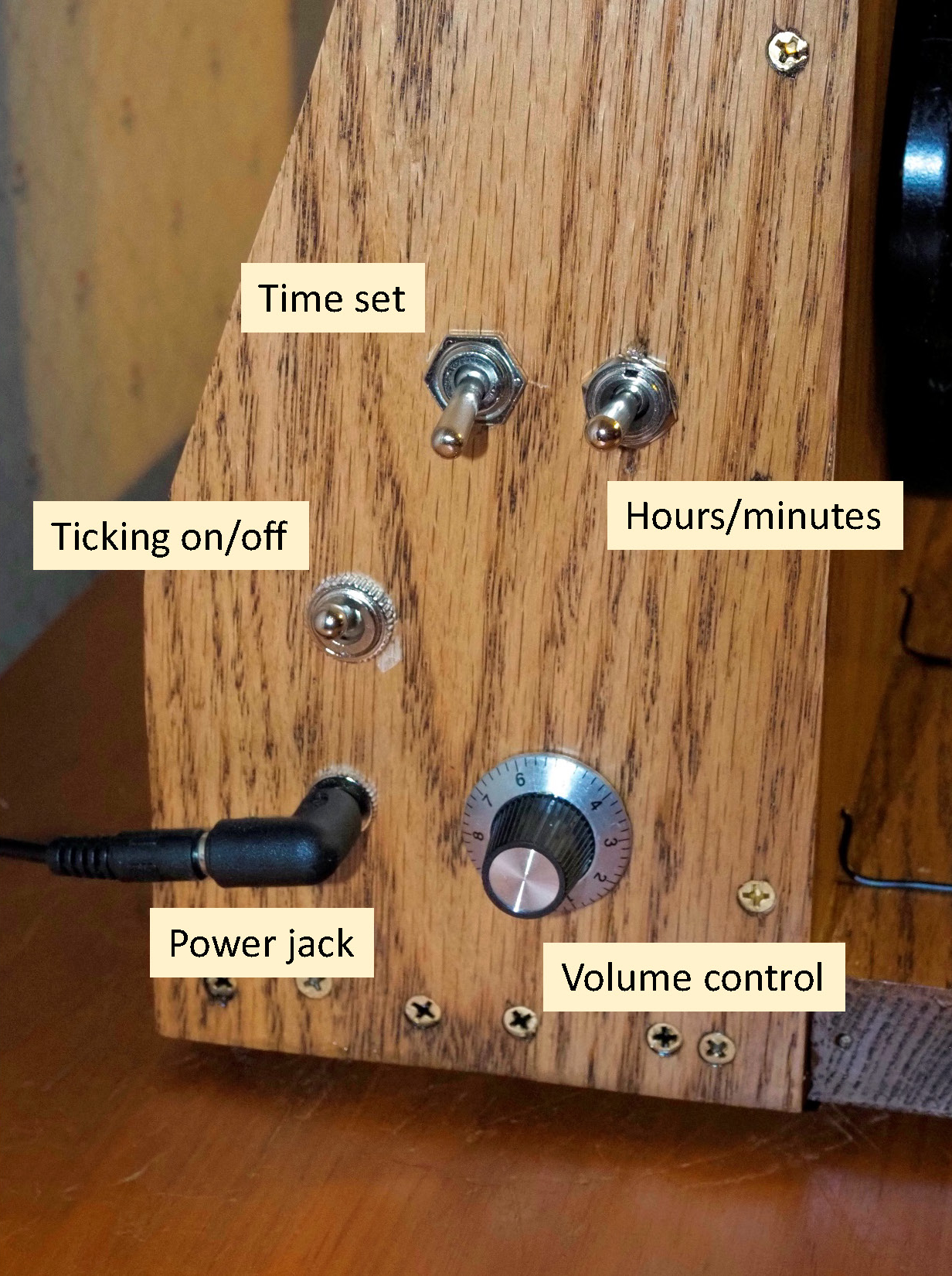
Side controls
There are several controls on the left side of the clock. The volume control sets the loudness of the ticking, chimes, gongs, and the speaking of the time, temperature, and humidity. The audio level is set before the sound is made, so it won’t effect the sound while it is playing. An easy way to set the level is to use the ticking to determine an approximate loudness, then ask the clock to say the time to see if it is where you want it. There is a switch to turn off the ticking if you don’t want it on continuously. Just set the switch up to tick, and down to mute the ticking. The other two switches are to set the time. See below.
There is no power switch. To turn the clock off, merely unplug the power supply from the power jack. The battery on the real-time clock will retain the time, so you will not need to reset it when plugging the power supply back in.
Setting the time
To set the time, set the top back switch to up. Increase the hour by moving the top front switch up. The clock will increase one hour at a time and speak the current hour. When the proper hour is reached, return the front switch to the center position. Increase the minute by moving the front switch down. As with the hour, the clock will increase the minutes one at a time, and speak the current value. When the desired minute is reached, return the front switch to center. Finally, when the actual time exactly matches the set time, move the back switch down. The set time will be spoken and the clock will reboot. You should be able to set the time very accurately. I suggest you use an internet time source such as time.is to coordinate setting the clock.
Care and feeding
Power
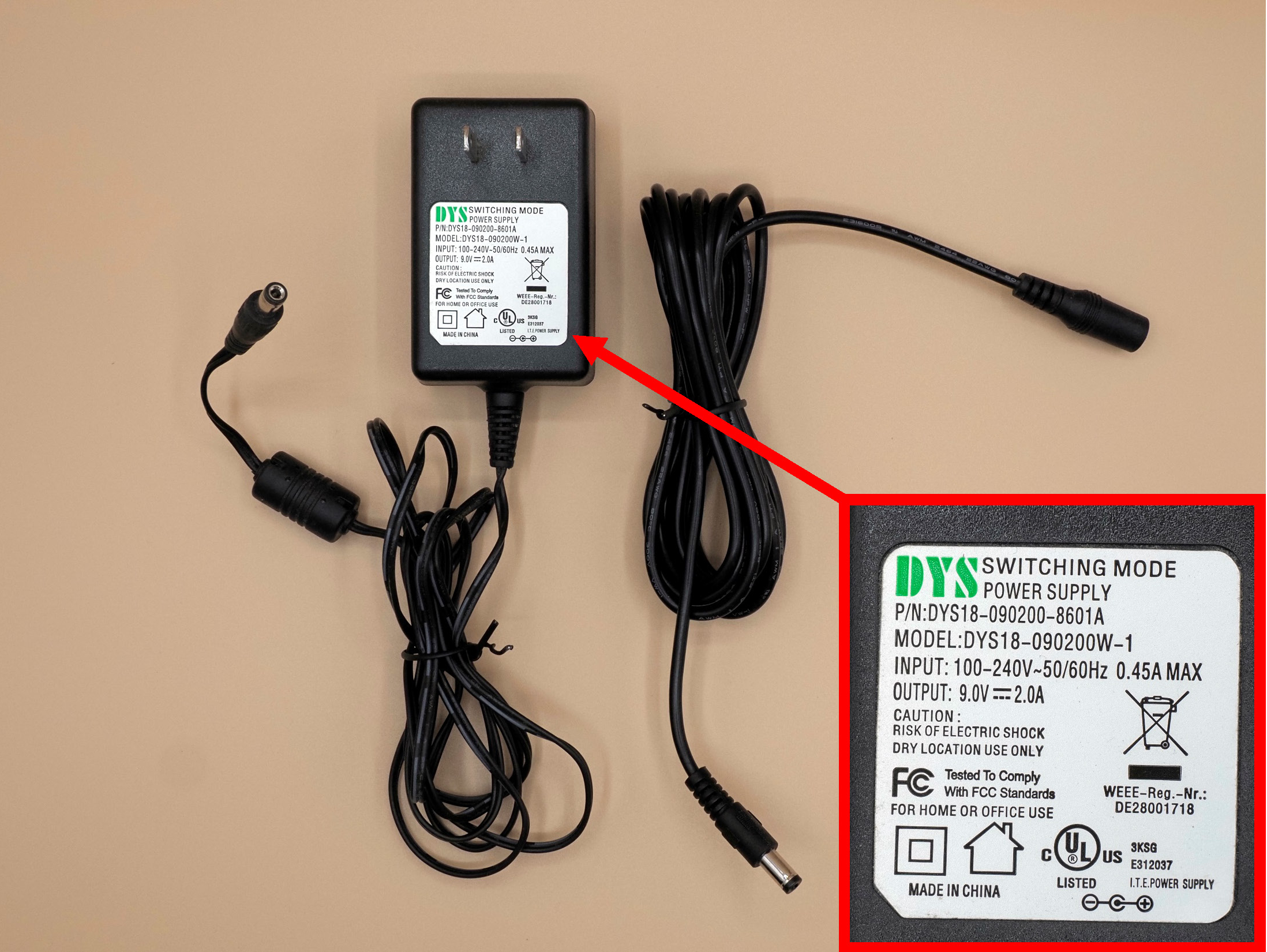
You must power the gadget by plugging a 9V DC power supply with a standard 2.1mm center-positive connector into the power jack (as shown above). Any supply with a current rating of 1A or higher should be fine (see picture). These power supplies are ubiquitous — just search for “9V arduino power supply” on Amazon or any other web commerce site and you will find numerous vendors. Just make sure the supply is 9V center-positive, or you will damage the controller. You can also find nice extension cords for these power supplies, as shown in the picture.
Battery
The real-time clock has a battery on board so that the time will be retained when the clock is unplugged. The battery should last at least five years. After that you may need to replace the battery. Open the black box and look for the real-time clock module. Remove the CR1220 battery and replace it with a fresh one. Be sure to note the polarity of the battery (the + side should be visible.) After you replace the battery you will need to reset the clock (see above).
Cleaning
Clean the gadget as you would any appliance. You can use glass cleaner on the meter glass, but be careful! The glass on any one of these these meters may be loose, and if you press too hard you may dislodge it.
Reading the Meter
Reading the hour
The hour is displayed on the top (Westinghouse) meter. The scale of this meter was originally designed to display current in the range 0-150 amps. I have calibrated the output of the controller so that the same display indicates the hour if you divide by ten. Thus, a reading of 30 amps is read as 3 o’clock, and 110 amps is 11 o’clock. In the picture to the right, the hour is 10 o’clock. Note that the hour hand does not move continuously between the hours (like on a normal clock) but instead points directly to the hour.
Reading the minute
The minute past the hour is displayed on the lower (Weston) meter, and can be read directly. The needle swings continuously along the minute scale. Note that since the meter is very nonlinear, the display may only be accurate to within a couple of minutes. To hear the exact time, you can touch the time touchpad, as described below. Also, the needle swings to the left in the morning, and to the right in the afternoon. Thus, it is immediately clear when the time is am versus pm. So, the time on the clock with the hours and minutes indicated in the pictures to the right is 10:40 am.
Using the touchpads
The clock will speak the temperature, time, or humidity when you touch one of the three touchpads. See the picture to the right. The loudness is determined by the volume control knob. Remember that the volume control does not work while the clock is speaking. Touch the pad just long enough for the clock to start speaking, then remove your hour finger. If you leave your finger on too long the clock will repeat.
Accuracy
Real-time clock
The real-time clock is a DS3231 high-precision module with an integrated, temperature-compensated crystal oscillator. The claimed accuracy is 2 ppm, which corresponds to about one second a month. So, you may need to reset the clock occasionally to keep the spoken time spot on.
Temperature/humidity
The clock uses a high-precision Silicon Labs Si7021 sensor to measure the ambient temperature and humidity. The sensor can be seen through a hole in the back of the black box. This is not a laboratory instrument, and you should not expect highly accurate readings. My guess is that the temperature should be good to about 2 degrees, and the humidity to about 5%, over the expected indoor range of readings. See the section below on the gadget operation for more information about accuracy.
Longevity
The Westinghouse ammeter is probably between 100 and 110 years old. The Weston meter is more modern, and is “only” about 65 years old. It may seem amazing that these meter still work, but most old meters are very well constructed and were designed for continuous use over a long haul. I hope that these meters have many more years of useful service in them, but there’s no way to tell when one or the other might crap out. If either stops working, the clock will continue to work and you can hear the time by pressing the touch pad. The clock will also continue to chime at the normal times. And the meters will always be beautiful antiques worth displaying!
How the clock works
The various operations of the clock are controlled using an arduino mega 2560 microcontroller. Time is kept using a DS3231 high-precision real-time clock module interfaced to the arduino through I2C. The time is set on the two meters by using digital output pins on the arduino. Inconveniently, the Westinghouse meter was designed to display a large amount of current — far more than can be supplied by the arduino. However, the meter operates by passing most of the current through an external shunt, and only allowing a small trickle to pass through the sensitive meter itself. Still, a full-scale deflection requires an application of 50 millivolts, and this draws more current than the arduino can supply. To overcome this, I use pulse-width modulation to control a DRV8871 DC Motor Driver, which can supply up to 3.6 A. Another driver is used to power the Weston meter, which also requires more current than can be supplied by the arduino. The motor drivers allow the direction of the current to be controlled, and this allows the Weston to display both positive and negative current readings. Using that, I can swing the needle left for am, and right for pm. These old meters are notorious for being both nonlinear and out of calibration, so I calibrated the meter through its range by using a 4th-order polynomial to best-fit the time to the displayed current. I expect that over time the performance of the meter will degrade and drift a bit. Even so, I wouldn’t be surprised if the more probable failure point is the solid-state arduino controller rather than the mechanical ammeter!
The ambient temperature and humidity are measured using a Silicon Labs Si7021 high-precision temperature/humidity sensor mounted in the housing. Although the sensor is placed behind a hole in the housing, the heat generated internal to the housing may make the temperature read a little high. The sensor is interfaced to the arduino on the I2C bus (along with the RTC). The sensor has a manufacturer-rated accuracy of +/- 1 degree Fahrenheit, and +/- 3% relative humidity.
Audio is generated using a music maker shield from Adafruit. This shield reads ogg or mp3 files from a micro SD card, then plays them through the speaker. The volume of an onboard amplifier is controlled digitally through pwm. The volume knob on the meter is a simple potentiometer interfaced to the arduino using an analog input pin. The potentiometer is a linear taper, and that does not correlate with our hearing, which is logarithmic. So, I compensate mathematically and supply a digital signal to the shield. The speech was downloaded as mp3 files from Amazon’s free text-to-speech service. The numbers are saved individually, then strung together to say the value of the time, temperature, or humidity, as needed. The chimes were downloaded as mp3 files from a source of free sound effects.
The touchpads are controlled using an MPR-121 capacitive touch sensor from Adafruit. This sensor interfaces to the arduino on the I2C bus, so there are three modules that simultaneously use the bus. The sensitivity of the sensor had to be adjusted to avoid spontaneous talking by the clock! Hopefully it will be quiet until asked to speak.